Setting On 555 Timer For Garage Door
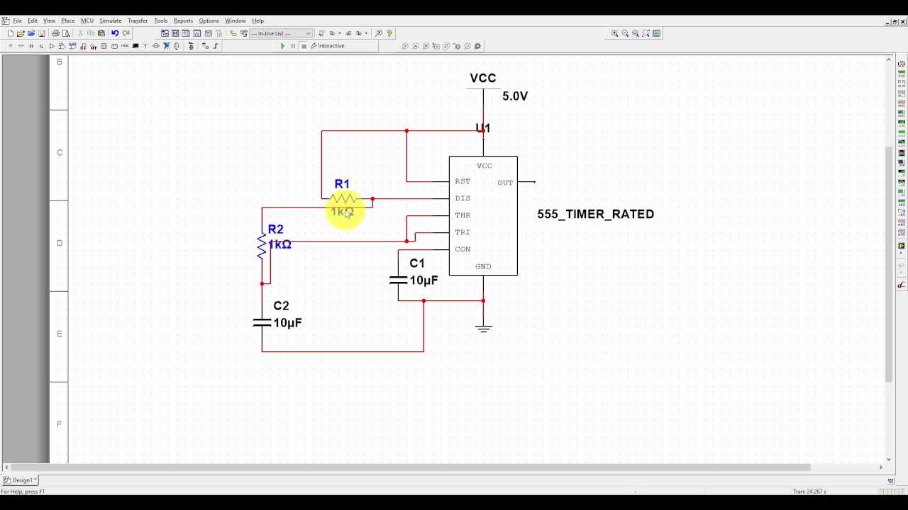
Multisim Tutorial 4 555 Timer Astable Mode Simulation Youtube

Bike Turning Signal Indicator Circuit Using 555 Timer Circuit Turn Ons Circuit Diagram

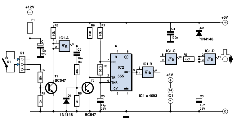
Door Alarm Using 555 Timer Door Designs Plans Electronics Circuit Electronics Projects Electronic Schematics

555 Timer Time Delay Circuit Timer Circuit Electronics Circuit
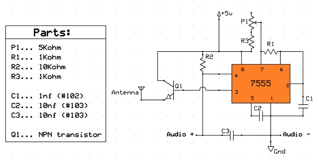
Am Radio Transmitter Using 555 Chip

Pin On Circuitos

All american craftsmans 108095 0001 mode u s a.
Setting on 555 timer for garage door. If it does not close rl1 in countdown mode will reset and open the door. We ran a piece of code to detect new incoming emails. Unless you have a carport it s very likely your garage has a garage door and thankfully there s no shortage of options to make your garage door opener smart. Fridge door alarm circuit used to sense the status of the door open or close when the door opens for a long time this circuit trigger 555 timer output and produces the high alarming sound.
Page 11 07 9111071330. Place the stepladder under the garage door opener power unit and climb up so that you have a clear view of the back end of the power unit housing. We will set up the email notification feature in myq app so when the garage door opens we will get an email notification in our email box. Page 1 garage door opener systems installation instructions and owners manual read these instructions carefully before installing or using this opener.
Garage door opener timer very robust and reliable timer that can accommodate a wide range of voltages making this timer super adaptable fast and free ship 734 568 0287 mon fri 8am 4pm est. Step 2 find the two dials on the back of the power unit. Start with a smart garage door opener garadget. After installation is completed place instructions in close proximity to garage door.
Because c4 does not have the time to fully discharge it should be at least three times the value of c5. When it resets again the door will close. If it is the one send from myq app saying door just opened we are ready to set up a timer to close the door. So today in this tutorial i am going to show how to make a simple fridge door alarm.
And that s good too because you ll get a lot of peace of mind when you switch to a smart opener.
Timer Circuit Page 6 Meter Counter Circuits Next Gr

555 Timer Based Simple Electronic Code Lock Circuit Diagram Circuit Timer Electronics Circuit
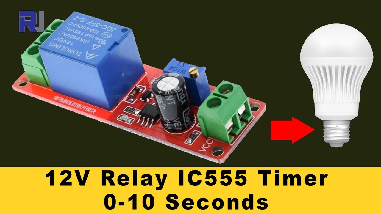
555 Timer Switch 12v Relay With Adjustable Time Test Review Youtube

Pin On Books Worth Reading
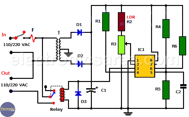
Automatic Night Light Using 555 And Relay Electronics Area

555 Timer Simulation In Proteus Youtube

Micro Inverter Schematic Diagram Google Search Teknologi

Diy Arduino Fingerprint Garage Door Opener Arduino Garage Door Opener Garage Doors

Pin On 555 Timer Circuits

Using Garage Door Safety Beams As Generic Photo Interrupter Sensors Casco Logix Garage Door Safety Garage Door Sensor Garage Doors

Pin On Electronic Circuit Diagrams
Voltage Controlled Oscillator Vco Circuit With A 555 Timer Voltage Controlled Oscillator Timer Synthesizer Diy

Unbiased Electronic Dice With Leds Using 555 Timer Electronic Dice Circuit Diagram Electronics

Stepper Motor Driver Using 555 Timer Circuit Diagram Stepper Motor Circuit Diagram Circuit

Esp8266 Serial Interface To Wifi Eletronica

555 Timer Amplifier Circuit Diagram Audio Amplifier Amplifier Circuit

Homemade Diy Howto Make Simple Doorbell Circuit Using 555 Timer Schematic Diagram Included Diy Electronic Kits Doorbell Diy Electronics

Garage Door Opener Electric Eye
Https Encrypted Tbn0 Gstatic Com Images Q Tbn 3aand9gcscxsgprgkupbhvquf0amevhcrgduosut Wattcizafgtcad Im Usqp Cau

Panic Alarm Circuit Diagram Working And Applications Circuit Design Circuit Diagram Circuit

Pin On Projects Lab

Circuit For Night Lamp Using 555 Engineersgarage Circuit Electronics Circuit Night Lamps

Astable Multivibrator Using 555 Timer Positivity Timer Electronics Circuit

Pin On Tecnologia

Unbiased Electronic Dice With Leds Using 555 Timer Electronic Dice Circuit Diagram Electronics
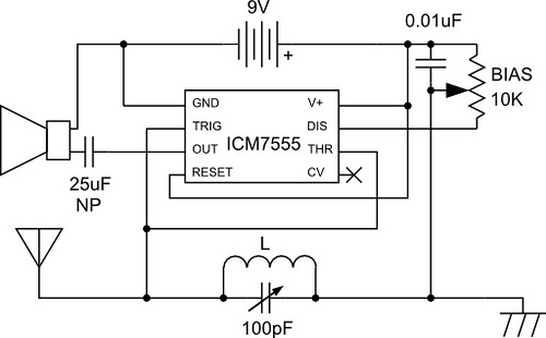
Am Radio Built Around Lm555

Pin On Okul Dene

Unique Simple Electrical Circuit Diagram Diagram Wiringdiagram Diagramming Diagramm Visuals Electrical Circuit Diagram Electrical Diagram Circuit Diagram

Arduino Based Home Automation Using Tv Remote Smart Home Automation Home Automation Home Automation System

Password Based Door Lock System Using 8051 Microcontroller Door Lock System Microcontrollers Circuit Diagram

Go Look Importantbook E Star C Stopwatch Timer Alarm Clock For The Regrretion Insert Of Triangle Market Amnimarjeslow Government 91220017 C Suta Ga Renzoku Teki Ni Idō Suru

Pin On Good Idea

Diy Motor Speed Control Arduino Motor Control Diy Electronics Electrical Projects

Timer Operated Relay With Digital Display Engineersgarage Relay Timer Pic Microcontroller

Https Encrypted Tbn0 Gstatic Com Images Q Tbn 3aand9gcra8j Ia5p8qbdd3h2c8i374wmttzp1j05mpq Usqp Cau

Plc Program For Bottle Filling Ladder Logic Ladder Logic Electrical Circuit Diagram Programmable Logic Controllers

Block Diagram Of Signal Waveform Generator Block Diagram Interface Diagram

Momentary Switch Delay Function Adventure Rider

3w Audio Amplifier Using Tda7056 Full Project With Circuit Diagram Audio Amplifier Amplifier Electronics Projects

In This Post We Are Going To Construct Led Strip Controller Circuit Using Arduino Which Can Turn On Off And De Arduino Led Led Strip Lighting Circuit Projects

Pin On Electronic Project Ideas

Dc 5v 12v 24v Delay Timer Relay Self Locking Delay On Off Time Switch Super 555 Timer Dc 5v 12v 24v Dc24v Amazon Com Industrial Scientific